peter (admin) -

Kubernetes Pod-to-Pod Communication
Here, we will learn how Pod-to-Pod communication works inside the Kubernetes networking model and understand how Pods running on different nodes communicate with each other using the cluster networking system.
Let's get started.
For this, we are already logged into both the Master node and the Worker node.
Create a Namespace
Let's move on and first create a namespace named deep.
The purpose of creating this namespace is to organize the Pods and other resources in a dedicated space where we can easily test Pod-to-Pod communication without affecting other system components.
peter@k8s-master:~$ kubectl get ns
NAME              STATUS   AGE
deep              Active   30d
default           Active   32d
kube-flannel      Active   32d
kube-node-lease   Active   32d
kube-public       Active   32d
kube-system       Active   32d
After successfully creating it, we verify the namespace list. Here you can see deep appearing with the Active status, which confirms that the namespace was successfully created and is ready to be used for our networking test.
Create Pod A
Now we create a test Pod named pod-a that will act as the source system for our communication test.
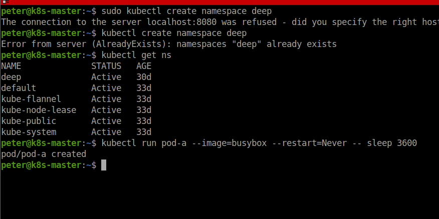
We instruct Kubernetes to start a single Pod using the BusyBox container image, which is a very small Linux environment commonly used for testing networking and basic commands.
The configuration also specifies that the Pod should not automatically restart, which means Kubernetes will run it once and keep it running without creating additional replicas.
Inside the container, we run a sleep process for one hour, which simply keeps the Pod alive so we can log into it and perform networking tests later.
The purpose of creating this Pod is to provide a running environment from which we will later send network requests, such as ping, to another Pod to observe how Pod-to-Pod communication works inside the Kubernetes cluster network.
Create Pod B
Similarly, we create another Pod named pod-b using the same BusyBox container so that we have a second running system inside the cluster.
kubectl run pod-b --image=busybox --restart=Never -- sleep 3600
The purpose of creating this second Pod is to provide a destination Pod for our networking test, because Pod-to-Pod communication requires at least two Pods: one that sends the request and another that receives it.
Verify the Pods
Let's verify the Pods we created.
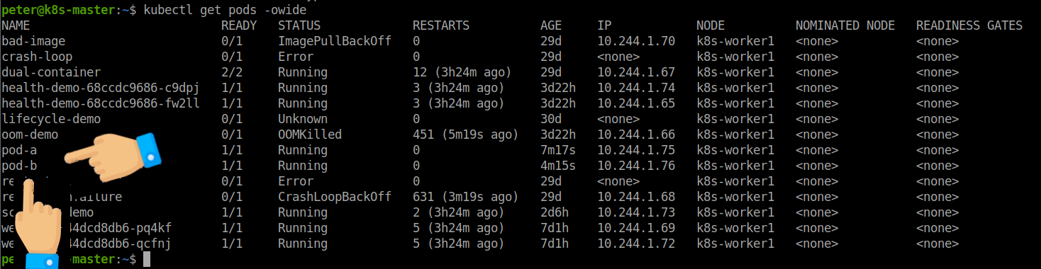
Here you can see that both pod-a and pod-b are successfully running in the cluster.
The output shows their Pod IP addresses, which means Kubernetes has assigned each Pod its own network identity inside the cluster network.
These IP addresses allow the Pods to communicate directly with each other.
Test Pod-to-Pod Communication
Let's move on and check if pod-a can reach pod-b through the cluster network.
For this, we go inside pod-a and send small network messages to the IP address of pod-b to see if it replies.
We perform the test with the following command
kubectl exec -it pod-a -- ping -c 4 10.244.1.75
Now we perform a ping test, where pod-a sends ICMP echo request messages to pod-b.
These ICMP messages are small network packets used to check whether another system is reachable on the network.
If networking is working correctly, pod-b should respond with ICMP echo reply messages, confirming that both Pods can communicate inside the cluster network.
After pressing Enter, you can see that the request is sent, but no reply is received, and the packet loss is 100%, which means communication is not working at this moment.
4 packets transmitted, 0 packets received, 100% packet loss
command terminated with exit code 1
This situation is useful because it allows us to troubleshoot the problem and understand why communication is failing.
Check the Worker Node Firewall
In many real environments, one possible reason for this issue is that the firewall on the Worker node is blocking Pod network traffic, which prevents packets from moving between Pods across nodes.
So let's move on to the Worker node and first add the required rules to the firewall
sudo ufw allow from 10.244.0.0/16
sudo ufw allow 8472/udp
sudo ufw allow 30000:32767/tcp
sudo ufw allow 30000:32767/udp
sudo ufw reload
This should allow our network, the he VXLAN traffic Flannel uses and our NodePorts
sudo ufw status numbered
Status: active
-- ------ ----
[ 1] 30000:32760/tcp ALLOW IN Anywhere
[ 2] 22/tcp ALLOW IN Anywhere
[ 3] 10250/tcp ALLOW IN Anywhere
[ 4] Anywhere ALLOW IN 10.244.0.0/16
[ 5] 30000:32767/tcp ALLOW IN Anywhere
[ 6] 30000:32767/udp ALLOW IN Anywhere
[ 7] 8472/udp ALLOW IN Anywhere
[ 8] 10.244.0.0/16 ALLOW IN Anywhere
[ 9] 30000:32760/tcp (v6) ALLOW IN Anywhere (v6)
[10] 22/tcp (v6) ALLOW IN Anywhere (v6)
[11] 10250/tcp (v6) ALLOW IN Anywhere (v6)
[12] 30000:32767/tcp (v6) ALLOW IN Anywhere (v6)
[13] 30000:32767/udp (v6) ALLOW IN Anywhere (v6)
[14] 8472/udp (v6) ALLOW IN Anywhere (v6)
After pressing Enter, the output shows that the firewall service is active and running, which means the Linux firewall is currently controlling network traffic on this node.
What did we do
We added the required firewall rules on the Worker node so that Kubernetes Pod network traffic is allowed to pass through the system firewall.
First, we allowed the Pod network range:
10.244.0.0/16
to be treated as trusted traffic, so packets coming from Pods are not blocked.
After that, we opened UDP port 8472, which is used by the Flannel networking component to carry Pod-to-Pod traffic between nodes.
Then we allowed the NodePort Service range:
30000-32767
which Kubernetes uses when Services are exposed through NodePort.
After adding these firewall rules, we reloaded the firewall service so that the new configuration becomes active.
Then we verified the firewall settings.
Here you can see that the Pod network range:
10.244.0.0/16
appears in the trusted sources list.
This confirms that traffic coming from the Kubernetes Pod network is now allowed by the firewall.
Test the Communication Again
Let's move back to the Master node and test the communication again from pod-a to pod-b.
After pressing Enter, you can now see that pod-a is successfully communicating with pod-b.
The output shows that all ICMP requests received proper replies, which means the packets are reaching the destination and coming back correctly.
Each line showing 64 bytes from the Pod IP confirms that pod-b received the request and responded back to pod-a.
The final result shows 0% packet loss, which confirms that the communication is fully working.
pod-a 1/1 Running 0 30m 10.244.1.79 k8s-worker1 <none> <none>
pod-b 1/1 Running 0 29m 10.244.1.80 k8s-worker1 <none> <none>
peter@k8s-master:~$ kubectl exec -it pod-a -- ping -c 4 10.244.1.80
PING 10.244.1.80 (10.244.1.80): 56 data bytes
64 bytes from 10.244.1.80: seq=0 ttl=64 time=0.123 ms
64 bytes from 10.244.1.80: seq=1 ttl=64 time=0.237 ms
64 bytes from 10.244.1.80: seq=2 ttl=64 time=0.115 ms
64 bytes from 10.244.1.80: seq=3 ttl=64 time=0.448 ms
4 packets transmitted, 4 packets received, 0% packet loss
round-trip min/avg/max = 0.115/0.230/0.448 ms
peter@k8s-master:~$ kubectl exec -it pod-b -- ping -c 4 10.244.1.79
PING 10.244.1.79 (10.244.1.79): 56 data bytes
64 bytes from 10.244.1.79: seq=0 ttl=64 time=0.094 ms
64 bytes from 10.244.1.79: seq=1 ttl=64 time=0.105 ms
64 bytes from 10.244.1.79: seq=2 ttl=64 time=0.467 ms
64 bytes from 10.244.1.79: seq=3 ttl=64 time=0.261 ms
4 packets transmitted, 4 packets received, 0% packet loss
round-trip min/avg/max = 0.094/0.231/0.467 ms
peter@k8s-master:~$
How Pod-to-Pod Communication Works
This demonstrates communication between Pods inside the Kubernetes cluster network, where one Pod sends network packets directly to another Pod using its Pod IP address.
The basic communication flow is:
Pod A
  ↓
Pod Network
  ↓
Flannel
  ↓
Worker Node Network
  ↓
Flannel on Destination Node
  ↓
Pod Network
  ↓
Pod B
This is a simple explanation of how Pod-to-Pod communication works in Kubernetes and how Pods running on different nodes communicate with each other using the cluster networking system.
Comments (0)
There are no comments yet. Be the first to comment.
Log in or register to leave a comment. all comments are subject to admin approval